Category: Drone

DSHOT with Python

Before learning about the DSHOT protocol my plan was to try writing the flight controller in Python. My main reason for this is that I’m hoping to use the Raspberry Pi’s Sense HAT for its gyroscope and other sensors to stabilise the quadcopter. The Sense HAT has its own Python module, making it very easy to read from the sensors.

Initially I did have a quick go at implementing DSHOT in Python, though I didn’t expect it to work.

import RPi.GPIO as GPIO
import time
import gc

# Hopefully reduce interruptions
gc.disable()

ESC_PIN = 19

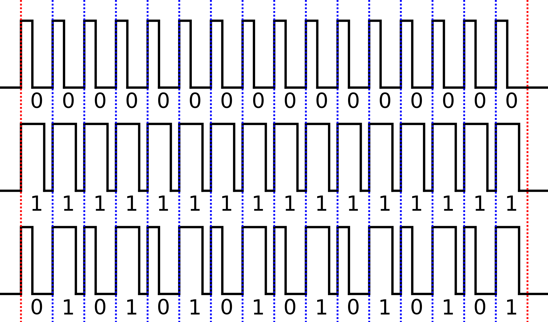
# DSHOT150 TIMINGS (6.68us per frame)
T0H = 0.00000250  # T0H = 2500ns
T0L = 0.00000418  # T0L = 4180ns
T1H = 0.00000500  # T1H = 5000ns
T1L = 0.00000168  # T1L = 1680ns

INTER_PACKET_DELAY = 0.00002  # 20us

def transmit_one():
    GPIO.output(ESC_PIN, GPIO.HIGH)
    time.sleep(T1H)
    GPIO.output(ESC_PIN, GPIO.LOW)
    time.sleep(T1L)

def transmit_zero():
    GPIO.output(ESC_PIN, GPIO.HIGH)
    time.sleep(T0H)
    GPIO.output(ESC_PIN, GPIO.LOW)
    time.sleep(T0L)

def inter_packet_delay():
    time.sleep(INTER_PACKET_DELAY)

def transmit_value(value, telemetry=0):
    # Add telemetry bit
    packet_data = (value << 1) | (1 if telemetry else 0) # Calculate and add CRC crc_sum = (packet_data ^ (packet_data >> 4) ^ (packet_data >> 8)) & 0xf
    packet_data = (packet_data << 4) | crc_sum # Output the packet for bit in range(16): if (packet_data >> (15 - bit)) & 1:
            transmit_one()
        else:
            transmit_zero()

if __name__ == "__main__":
    # Setup GPIO
    GPIO.setmode(GPIO.BCM)
    GPIO.setup(ESC_PIN, GPIO.OUT)

    # Send reset value to arm the ESC
    print("RESETTING")
    for _ in range(20):
        transmit_value(0)
        inter_packet_delay()

    # Send values from 48 (throttle = 0) to 100
    for throttle in range(48, 100, 1):
        print("Throttle = {}".format(throttle))
        for _ in range(1000):
            transmit_value(throttle)
            inter_packet_delay()

    # Send reset again
    print("RESETTING")
    for _ in range(10):
        transmit_value(100)
        inter_packet_delay()

This code illustrates quite clearly (I feel) how the protocol is supposed to work, however the problem is that the length of time that time.sleep() takes is not guaranteed to be the amount requested, just that it will be at least that amount of time. My understanding is that the OS may context switch to do something else, which according to this benchmark can take in the order of microseconds (though that is for Intel’s architecture, Raspberry Pi’s ARM architecture may be different). In fact:

pi@raspberrypi:~ $ python -m timeit "time.sleep(0.000000001)"
100000 loops, best of 3: 2.07 usec per loop
pi@raspberrypi:~ $ python -m timeit "time.sleep(0.000000002)"
100000 loops, best of 3: 2.05 usec per loop
pi@raspberrypi:~ $ python -m timeit "time.sleep(0.000001)"
10000 loops, best of 3: 74.8 usec per loop
pi@raspberrypi:~ $ python -m timeit "time.sleep(0.000002)"
10000 loops, best of 3: 76 usec per loop

Trying to sleep for one or two nanoseconds results in a delay of at least two microseconds, and strangely trying to sleep for one or two microseconds results in a delay of around 74 microseconds. This is clearly not going to work for the timings I’ve requested. In fact, I’ve now measured the output of this program with an oscilloscope.

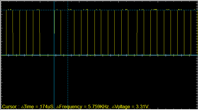
The waveform was essentially just a square wave with a period of about 174 microseconds. It looks nothing like the DSHOT frame I was trying to send and each period is around 26 times as long as it was meant to be (6.68 microseconds). I have since learned that the ESCs support multiple protocols (i.e. PWM based signals), which explains the little accident I had after running this code for the first time.


WARNING

These motors are powerful and the propeller blades spin fast. Keep out of the way of them and ensure that your quadcopter cannot accidentally fly toward you or anyone else. This is especially important when trying to develop your own control software – don’t start by putting the propellers on!


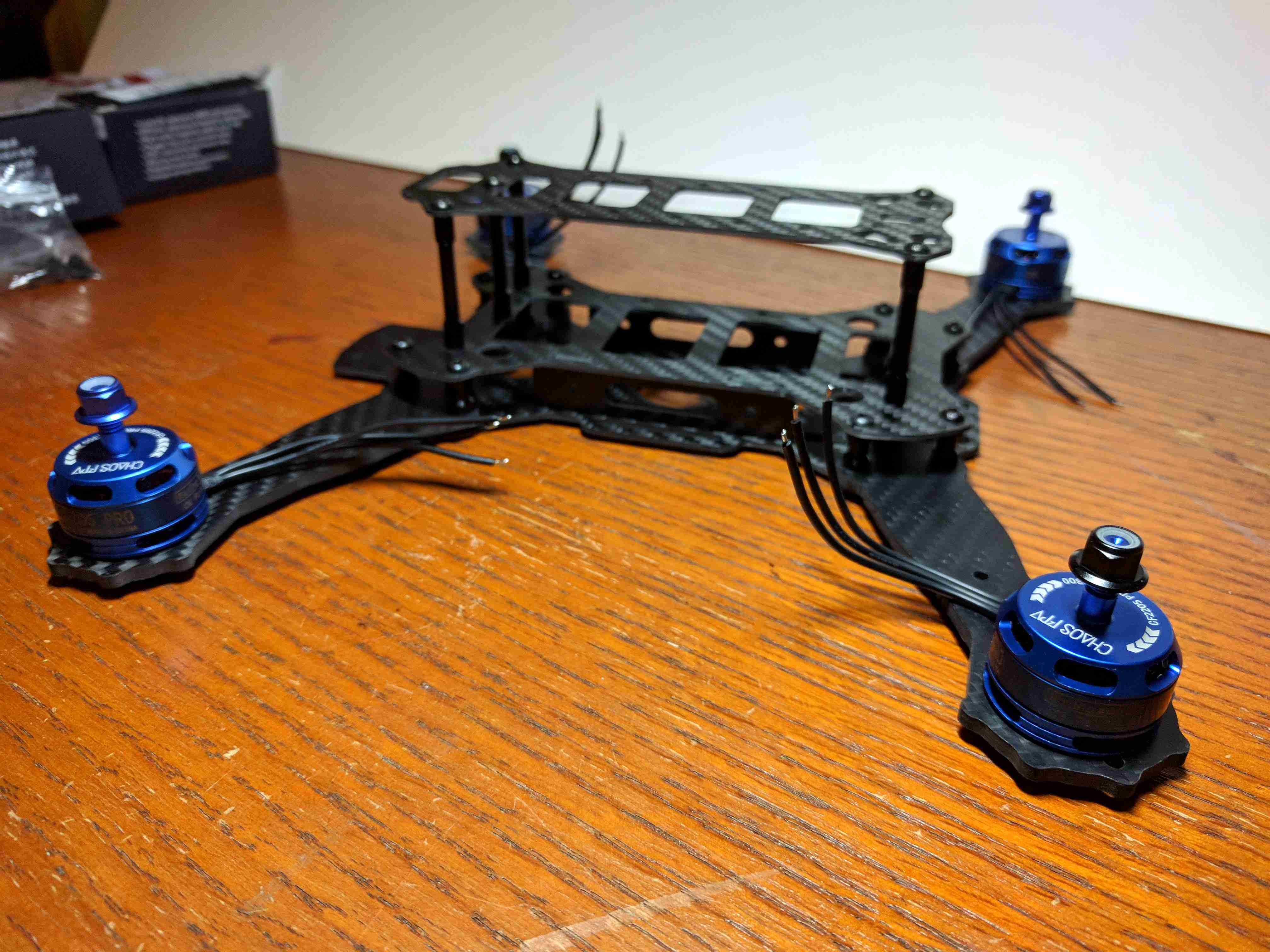
The quadcopter I’d built was on our coffee table in the living room and I was trying out different things trying to get the motor I’d soldered on to do something. I ran the above code (or something very similar) for the nth time expecting nothing to happen. Suddenly the propeller started turning at high speed, lifting itself up and pivoting towards my girlfriend’s foot which was resting on the table. Fortunately, it then cut through the ribbon cable which I’d used to connect the Raspberry Pi to a breadboard and then to the ESC which stopped the signal and thus the motor.

This was incredibly lucky. Please don’t do this!

So, I learned that using Python along was not going to work in any sensible way. After some reading I decided I would try using busy loops (looping many times doing very little, not voluntarily giving up control to the operating system) to get the accurate delays I wanted. The disadvantage of busy loops is that they take up a whole processor essentially doing nothing, which is not good for power efficiency or allowing the system to do anything else, but if it worked it would be a start. Due to the documentation on DSHOT being slightly lacking I wanted to give this the best chance of working and so I decided I would do this in C to eliminate any overheads that the Python interpreter might bring. I’ll discuss how this went in my next post.

DSHOT in the Dark

I was excited to start attempting to make the motor turn. It has proved to be more tricky than expected, however.

Everything I’d skim-read up until now had suggested that ESCs used Pulse Wave Modulation (PWM) for their input signals. This generally means creating an on-off signal at some frequency and varying the duty cycle (the amount of time an on-off signal is in the ‘on’ state) to communicate what percentage of power should be sent to the motor. I now understand that this was the case until fairly recently, but the ESCs I have bought use a digital protocol called DSHOT instead (it’s in the product name, but I had no idea what it meant at the time). As far as I can tell this protocol was conceived by some engineers/enthusiasts on a forum (the original thread, I think) and has become a somewhat popular standard for controlling ESCs for quadcopters/multicopters.

Through reading through a number of articles about the protocol (e..g here and here) I think I have a basic understanding of it. The code that runs on the ESCs is available here and the code that runs on popular flight controllers is here, so in theory it’s possible to figure out exactly what’s going on, but the ESC code is written in assembly for an architecture I’ve never studied and the flight controller software is in C which runs on an embedded system I’m also not familiar with.

Using the articles and a bit of the flight controller code I think I’ve pretty much figured out what’s expected which I’ll explain shortly. The only problem is that it’s made me realise a bit of an issue with my original plan – the protocol requires the input signal to be toggled with sub-microsecond accuracy. Given that Linux is a multi-tasking operating system, you cannot rely on your code being run uninterrupted and I’m worried that a context switch at the wrong time might lead to a physical crash.

The DSHOT protocol consists of transmitting 16-bit packets to the ESCs: an 11-bit throttle value; one bit to request telemetry (or to indicate you want to change a setting) and a 4-bit checksum. Originally, at least, there were three defined speeds for the protocol, DSHOT 150, DSHOT 300 and DSHOT 600. The numbers refer to the theoretical maximum speeds of data transfer in kilobits. Given the timing concerns above I am going to focus on the slowest version, DSHOT 150.

Each bit of a DSHOT packet is transmitted by setting the signal voltage high and then low. To communicate a ‘1’ the high portion of the wave must be longer than the low portion, and vice-versa to communicate a ‘0’. There are oscilloscope images at some of the above links which illustrate this a bit better. The eleven throttle bits are send first, starting with the most significant bit, then the telemetry bit and finally the four checksum bits. The code to calculate the checksum can be found in the cleanflight flight control software.

I haven’t found any articles listing the expected timings for DSHOT 150, but this article lists them for DSHOT 600. I them multiplied by four to get the DSHOT 150 timings, but I think they are calculated as follows:

  • 150000 bits ber second = 1/150000 = ~6.67 microseconds (μs) per bit
  • This matches the timings from the above article multiplied by four, so approximate timings for the waveforms are:
    • T0H (time for the high portion of a zero bit) = 2500μs
    • T0L (time for the low portion of a zero bit) = 4180μs
    • T1H (time for the high portion of a one bit) = 5000μs
    • T1L (time for the low portion of a one bit) = 1680μs

None of the articles I’ve read have explained why the timings are this way. It seems that the zero bit just needs to have a longer low portion and vice-versa for the one bit, and I think the whole idea is that the exact timings for each is not that important. This is one of the touted advantages over PWM based protocols (of which there are a few) in that timing variations do not lead to incorrect throttle values being sent to the ESCs.

Now I’ve explained how zeroes and ones are transmitted, I’ve prepared some example frames that could be sent to an ESC:

In DSHOT, the throttle values 0-47 are reserved, so 48-2047 give 2000 steps of throttle resolution. Of the reserved values, 0 is reset or disarmed and the others are various settings or requests for information. There is a concept of bidirectional communication using some output on the ESC but I’m not sure whether my ESCs have this output (certainly not without removing the shrink-wrap plastic) and I’m not interested in it for now. When sending any values 1-47 the telemetry bit should apparently be set. In the betaflight code the only settings that seem to be implemented are the spin direction (normal or reversed) but not the save settings command, so I’m not sure what’s going on. Settings commands should apparently be sent at least 10 times, presumably for reliability. It’s difficult to gather whether the things that the flight controller software do are required for interfacing with a DSHOT ESC or if it’s just best practice.

In the above image, the first frame, 0000000000000000 is the special ‘reset’ packet. I’m not sure of its precise function. The second two frames are valid throttle values, 111111111111 and 0101010101010101. These were just convenient examples and represent maximum throttle (2047) and a throttle value of 682. The second two examples include the “telemetry” bit set to one.

The last four bits are the checksum which is supposed to provide a some assurance that the bits read were the bits sent (if there were any bit misread the checksum won’t match the data). I couldn’t find the definition for this checksum anywhere other than the cleanflight/betaflight code, so here is an intuitive explanation. The related code is here:

// compute checksum
int csum = 0;
int csum_data = packet;
for (int i = 0; i < 3; i++) {
 csum ^= csum_data; // xor data by nibbles
 csum_data >>= 4;
}
csum &= 0xf;
// append checksum
packet = (packet << 4) | csum;

Taken from the cleanflight code on github.

So essentially start with 0 and XOR the 12 bits of data we want to send (11 throttle bits, 1 telemetry request bit) with that (and basically get the same thing, 0 XOR 0 = 0 and 1 XOR 0 = 1). We then right-shift the data by four bits and XOR the result with the value obtained in the previous step and repeat this again. An easier (but less generic) way of looking at it might be this:

csum = (csum_data ^ (csum_data >> 4) ^ (csum_data >> 8)) & 0xf;

The first bit of the checksum is therefore made up of the first bit of the data XORed with the 5th and the 9th, the second bit is made up of the second bit of the data XORed with the sixth and the tenth etc. In theory if any one of those bits gets read as the opposite value, the the checksum will be incorrect.

As described above, each bit takes 6680ns to transmit. This means a frame takes 16*6680=106880ns to transmit. This means that the maximum rate that we can update the ESC’s speed is 1/0.000106880=~9356Hz, however that would be with no gaps in between frames. Various articles state that the theoretical maximum update rate for DSHOT 150 is 8kHz, which would mean a (1/8000)-0.000106880=0.00001812s gap between frames (just under 2 microseconds), however the betaflight wiki page for DSHOT states that the maximum rate used for DSHOT 150 in betaflight is 4kHz. This means a (1/4000)-0.000106880=0.00014312s gap (~14 microseconds) in between frames. It sounds like the exact spacing isn’t too important and for my experimentation a lower value would be useful (to allow some time to do some other computations), so we’ll see what happens.

From the product name of the ESCs I bought (listed in the first post) you can that part of it is “BLHeli_S”. This is the firmware installed on the ESCs, and the code (in assembly) can be found here. Inside the “BLHeli_S SiLabs” directory there is a PDF manual which describes some things about the firmware, though it does not seem as if it was written to help people interface with it.

With that all out of the way, the next post will go into some experiments I’ve been trying in an attempt to control an ESC with my Raspberry Pi.

Update 2017-12-04: added a bit about update rates.

Some soldering later

Now that the motors were secured to the frame, I wanted to finally have a go at making one of the motors spin. This meant soldering some bits together to allow me to power a speed controller and for it to send signals to a motor.

The first step was to solder the battery connector (a standard called XT60) to the Power Distribution Board (PDB). The PDB has two functions: to distribute power from the battery to the four ESCs (by basically providing four sets of pads to solder things to) and to act as a voltage regulator to step down the 14.8V of the battery to 5V with which I can power the Raspberry Pi. The voltage regulator doesn’t seem to be present on all PDBs because it some ESCs contain one and people sometimes use one of them to power their flight controller. For this reason, they’re sometimes called Battery Elimination Circuits (BECs) because it means that you don’t need a separate 5V battery (as far as I can tell).

My soldering is not great so I was slightly concerned that I may have shorted the two battery terminals when attaching the connector. I tested this by connecting an LED to a battery and connecting a wire to each terminal as part of the circuit to see if there was a connection. During this test the LED did come on, suggesting that I had connected them together, but looking closely I couldn’t see where this had happened. Though it was risky (in terms of both damaging the battery or even causing it to explode) I decided to connect it anyway and fortunately found that everything was fine and some LEDs on the PDB came on, confirming that all was well.


After soldering the connector to the PDB (slightly awkward given that there were just two big holes to cover with solder) I then soldered the red and black wires coming from one of the ESCs to positive and negative pads on the PDB and the three wires coming from one of the motors to the three pads on the ESC. The order of the motors wires shouldn’t matter, but it might turn out that the motor spins the wrong way. If this is the case I will have to un-solder two wires and swap them around.

Plugging the battery in again produced some very exciting beeps. I’ve since learned that the ESCs produce this noise by making the motors vibrate, which seems quite clever.

In theory I now have enough to try making the motor spin.

Motoring On

As soon as the frame was built, I wanted to attach the motors to see how it looked and check that the propellers I’d ordered would fit without hitting the frame. When I first opened one of the motor boxes I thought that the manufacturers had been exceptionally generous by providing twice as many screws as necessary. I then noticed that some are shorter than others.

I used the shorter screws to attach the motors to the frame because they seemed sufficient and the longer ones looked like they’d go further into the bottom of the motors that I was comfortable with.

There are two types of motor, or so I thought. When buying them you can usually choose either Clockwise (CW) or Anti/Counter-Clockwise (CCW), as for a quadcopter you want two propellers spinning CW and two CCW (though it might be fun to experiment with what happens if you don’t – I suspect the quadcopter will spin). I didn’t think too much about this and assumed that there was some sort of optimisation inside the motors for turning in a certain direction. Apparently the only difference is the threading on the spindle and nut such that when spinning in a certain direction, the nut will self-tighten, as opposed to undoing itself.

The motors I bought are 2300kV, which I believe means they will turn at 2300rpm per voltage of input. I have glanced over some discussions of what this means and what I took away was that a lower number will provide more power at a slower speed, and vice-versa. I’m hoping that these motors will be just about powerful enough to turn 6″ propellers fast enough to lift my quadcopter, though I haven’t done any calculations. There is a table on this page which seems to suggest that for my frame size I want to use 2000kV-2300kV motors with 6″ propellers. Ideally I would have got 2000kV motors, but the website I was ordering from had a convenient and well priced combo pack which seemed like the easiest way to get started.

Building the frame

Building the frame seemed like the logical thing to do first. It will provide a base to attach the motors to, which will allow for testing. I have read that you shouldn’t run the motors without any load attached, and I don’t have anything else to hold the motors to with propellers attached.

The instructions that came with the kit are just about sufficient to understand what to do. There are lots of parts and I was initially a bit unsure of how to proceed, however, I started at the bottom and built up. It was quite straightforward in the end and required only a small Allen key. There is a sort of canopy that goes on the top which I decided not to put on just yet as it would make it harder to access the internals and it would also add unnecessary weight.

There were a number of factors that went into choosing this frame, and I’m still a little unsure about it. From looking around, the 250mm size (measured approximately from the centre of diagonally opposite motors) is fairly popular with racing drones, so I assume that it is some sort of size category. The frame I got is 270mm which I hope will allow me to build something slightly more powerful (e.g. with larger motors and propellers) to account for the extra weight of a Raspberry Pi and Sense HAT over a standard flight controller.

Charging the battery

The first thing I could do to play with the new bits I had bought was to charge the battery.

Battery and charger

I had read a little bit about batteries before making my order. There are a number of specifications to look out for. Firstly there is the number of Ss. My understanding is that LiPo batteries are sold with different numbers of cells, with each cell producing 3.7V. Thus a 4S battery like the one I have bought produces (4*3.7) or 14.8V. According to this, the S stands for Series and it sounds like you can also get batteries with more cells wired in parallel at the same time (which would increase current at the same voltage). Motors and ESCs seem to be able to handle a range of voltages, and the higher the voltage the more power and thus thrust you can get from a particular motor/propeller combination. When looking around, it seemed like people used either 3S or 4S batteries with the size of quadcopter I was planning on building (~250mm, though I’ve bought a 270mm frame), so given that one of the comments I’ve received is “Isn’t a Raspberry Pi a bit heavy for that?”, I thought I’d go for the more powerful option.

There are other numbers that are relevant after choosing a voltage: capacity (measured in milliampere hours (mAh)) and C rating (coulombs, presumably), which refers to how fast the battery can discharge its energy. The higher the capacity, the longer the battery will last when using the quadcopter, but the battery is also likely to be bigger and heavier so it’s a trade-off. Unmanned Tech Shop suggested on one of their product pages that a 1300mAh – 1550mAh battery was suitable for a frame about the size I was looking, though I can no longer find that page (they all seem to suggest 1300mAh now), so we’ll see what happens. As for the C rating, I’m unsure of how to calculate what’s reasonable for a particular quadcopter. The one I got is 75C (which I suppose means it can deliver 75A/s, so at 14.8V that’s 1110W.. really?) but I don’t yet know if it was necessary to get that over the more common 45C batteries. The one I got seemed to be a good compromise between the different specifications and price.

The chargers require to charge LiPo batteries are known as “balance chargers”. As well as having a power output to charge the battery, they also have input sockets which you plug the battery into so that the charger can tell how charged the individual cells of the battery are. I assume that this is important because lithium batteries can sometimes catch fire and so even charging is good for safety. Some chargers also have an input for a temperature sensor to make sure that batteries do not overhead, although mine does not, so I’ll only be charging it while I’m in the room. The charger I bought can also charge at 1A, 2A or 3A. The higher the current, the faster that battery will charge, but it depends on a battery’s charging C rating (different from the discharging C rating above) as to what it can safely handle. I wasn’t aware of this when I ordered mine, and the documentation is a bit confusing (the leaflet with the battery says 1C but the battery itself says 5C) so for safety I charged at 1A. From what I’ve read, you can work out the maximum charging current by multiplying the charging C rating by the battery’s capacity, so if it’s a 1000mAh battery with a 1C charging rating, you can charge it at 1A. If it had a 5C charging rating, you could charge it at 5A.

I didn’t time how long it took to charge that battery (and I’m unsure whether it came partially charged or not), but the charger seemed to do somethings, flashed some lights (to show it was discharging individual cells) and eventually showed a green light to show that the battery was ready.

It’s arrived!

A cardboard box

It arrived! After more than a year of claiming I was going to build a quadcopter/drone, I finally ordered the parts to do so. The plan is to build a quadcopter using off-the-shelf parts, but instead of buying a flight controller I will use a Raspberry Pi 3B and attempt to write my own flight control software. This is likely to take a long time and I plan to document my progress here. My only experience with quadcopters is having a go with a small one (a Syma X11C) and I’ve never studied aviation.

It feels like it should be straightforward to write the software to make a quadcopter hover: given input from some sensors (accelerometer, gyroscope), output signals to motors to try to maintain the current position and angle, i.e.run all the motors at some speed and if the sensors suggest that one side is dropping down, increase the speed of the motor(s) on that side. I am certain that it will be more complex than that but half the enjoyment of this project will come from finding out how and why.

I’m pretty excited to get started. The first stage of the project will be putting all the components together which is like getting a new Lego kit. The next will be soldering the electronic components together and exercising my electronics interest. The last will be trying to write some code to make the thing fly, which is something I’m looking forward to a lot.

A while ago I ordered a Sense HAT for my Raspberry Pi because it contains an accelerometer, a gyroscope, a magnetometer (compass), a barometer (for altitude) as well as a hydrometer and a thermometer. It also has a super cool LED display. This seemed like a very convenient way of getting the sensor inputs I thought I needed, though it remains to be seen whether it will be sufficient. My main concerns are the speed and accuracy of the sensor data.

I had considered buying just some of the parts initially just to see whether I could get a motor to run. However, when I started adding up all the bits I would need just to do that, it seemed to make sense to just order everything at once. The motors generally used for drones of the size I was thinking seem to be 3-pole brushless motors. Due to the power requirements of these motors, it’s not possible to run them directly from the Raspberry Pi outputs. For this reason, and the need to generate accurate sequences of pulses to the three poles to make the motors turn, Electronic Speed Controllers (ESCs) are used. These devices take a higher voltage power input (generally from a Lithim-Polymer (LiPo) battery) and a signal input (e.g. from a flight controller) and generate the three signals required to drive a motor at a particular speed. Along with a motor therefore, I would also need to buy a speed controller, a battery (or a good bench power supply, ESCs can draw 30A or more) and a battery charger, just to make a motor turn. This drove my decision to buy the four motors I’d need, four ESCs, a battery, a charger, a Power Distribution Board (PDB) with a Battery Elimination Circuit (BEC), propellors and a frame to hold it all together.

I ordered from Unmanned Tech Shop as they had everything I thought I needed and for a reasonable price.

An opened cardboard box

Inside the box were the following bits:

  • 1 × SkyRC e430 LiPo/LiFe (2-4S) Balance Charger
  • 1 × RoboCat 270 Mini FPV Quadcopter Frame (White)
  • 1 × 6×30 ABS Plastic Propeller Pack (4 x CCW, 4 x CW) (Black, but one set arrived in orange, which is fine)
  • 1 × Streak Mini PDB with BEC (120A)
  • 1 × TATTU 1550mAh 14.8V 75C 4S1P Lipo Battery Pack
  • 4 × Chaos BLHeli_S Dshot ESC (20A)
  • 1 × ChaosFPV CF2205 PRO Motor Pack (2 x CW, 2 x CCW) (2300kV)

I will go into more detail about the components in later posts as I come to use them, but for now I think I might just about have everything I need to make something that can fly!