Month: November 2017

Some soldering later

Now that the motors were secured to the frame, I wanted to finally have a go at making one of the motors spin. This meant soldering some bits together to allow me to power a speed controller and for it to send signals to a motor.

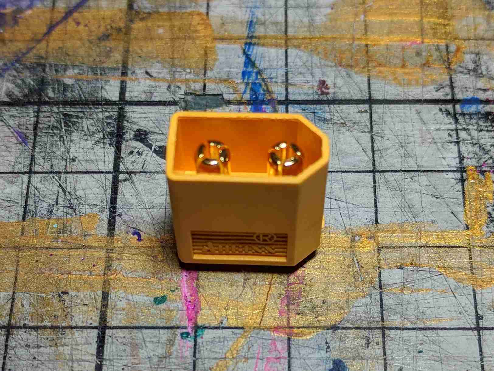
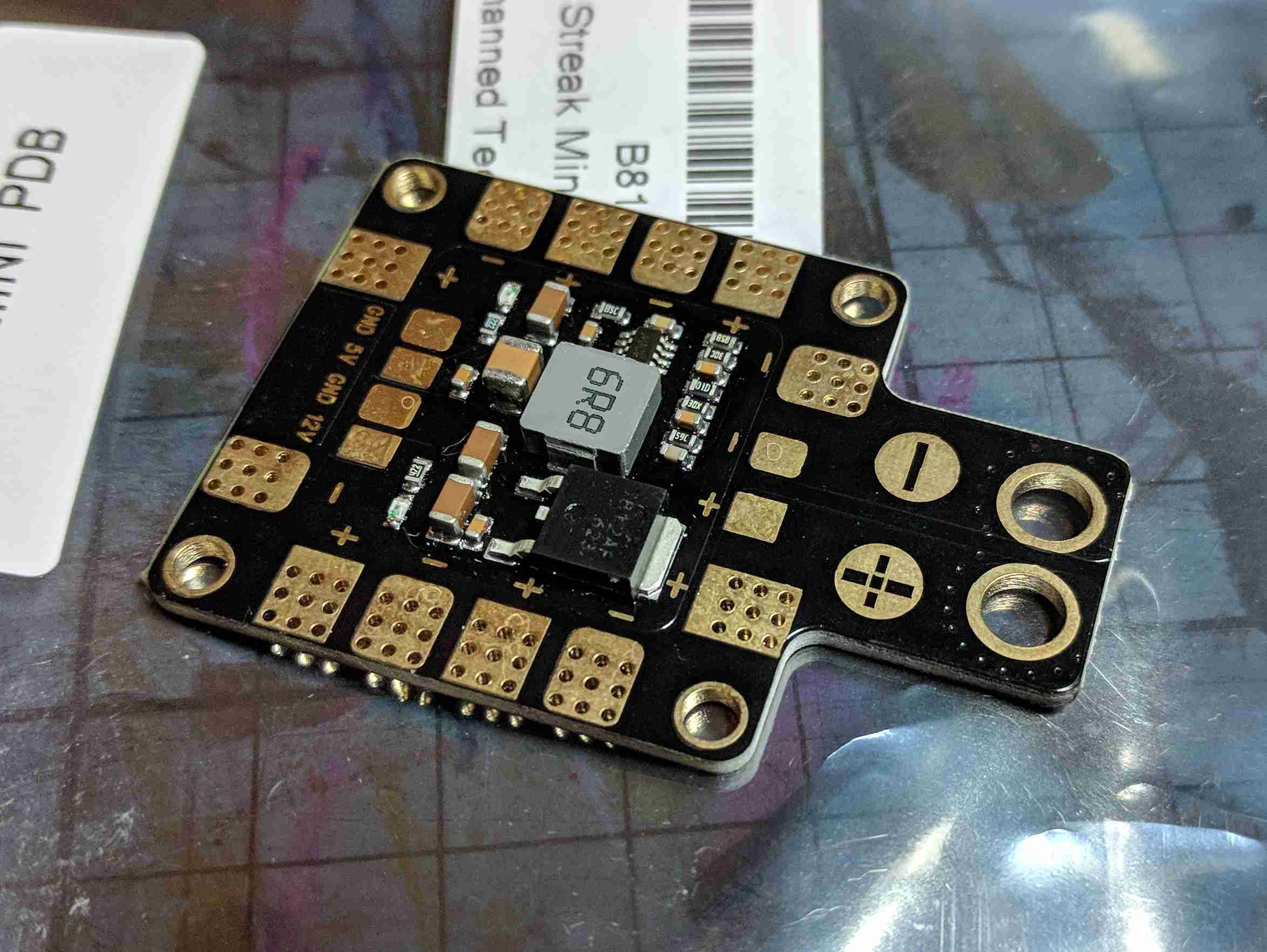
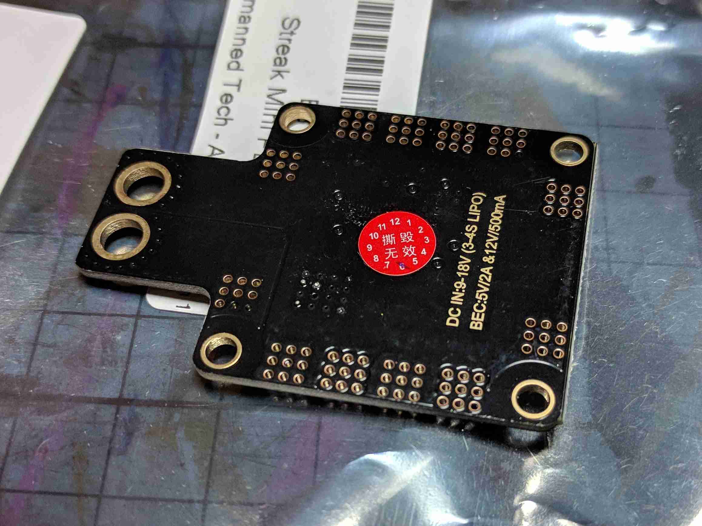
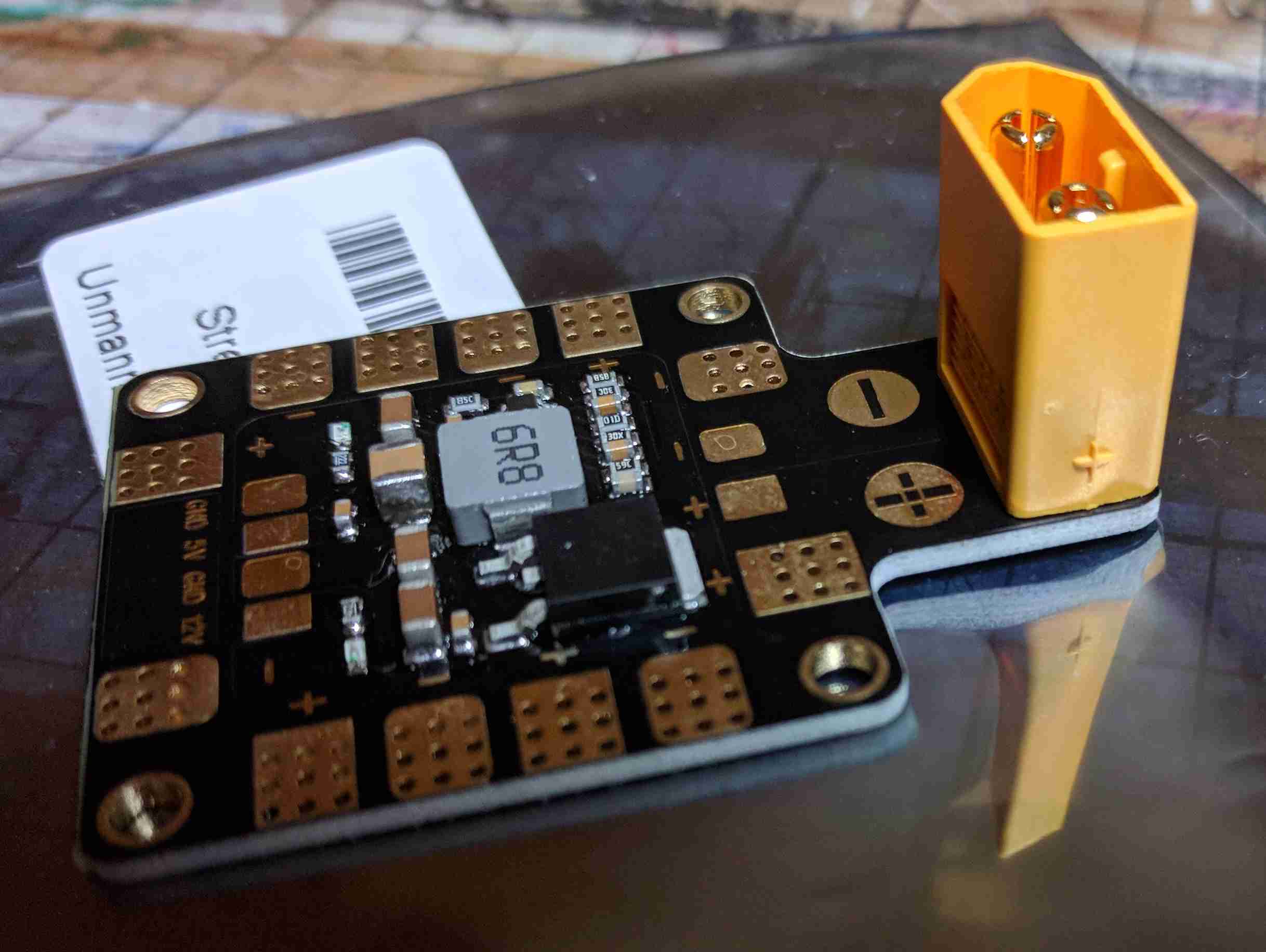
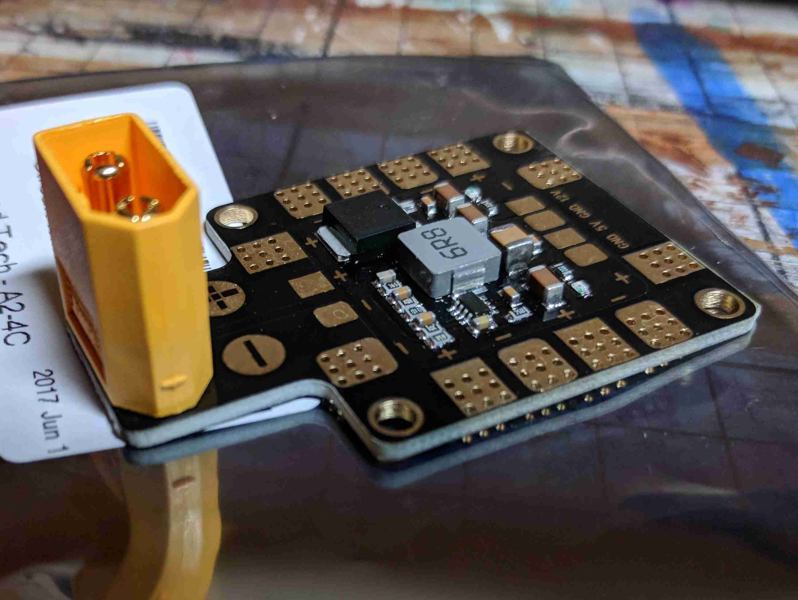
The first step was to solder the battery connector (a standard called XT60) to the Power Distribution Board (PDB). The PDB has two functions: to distribute power from the battery to the four ESCs (by basically providing four sets of pads to solder things to) and to act as a voltage regulator to step down the 14.8V of the battery to 5V with which I can power the Raspberry Pi. The voltage regulator doesn’t seem to be present on all PDBs because it some ESCs contain one and people sometimes use one of them to power their flight controller. For this reason, they’re sometimes called Battery Elimination Circuits (BECs) because it means that you don’t need a separate 5V battery (as far as I can tell).

My soldering is not great so I was slightly concerned that I may have shorted the two battery terminals when attaching the connector. I tested this by connecting an LED to a battery and connecting a wire to each terminal as part of the circuit to see if there was a connection. During this test the LED did come on, suggesting that I had connected them together, but looking closely I couldn’t see where this had happened. Though it was risky (in terms of both damaging the battery or even causing it to explode) I decided to connect it anyway and fortunately found that everything was fine and some LEDs on the PDB came on, confirming that all was well.


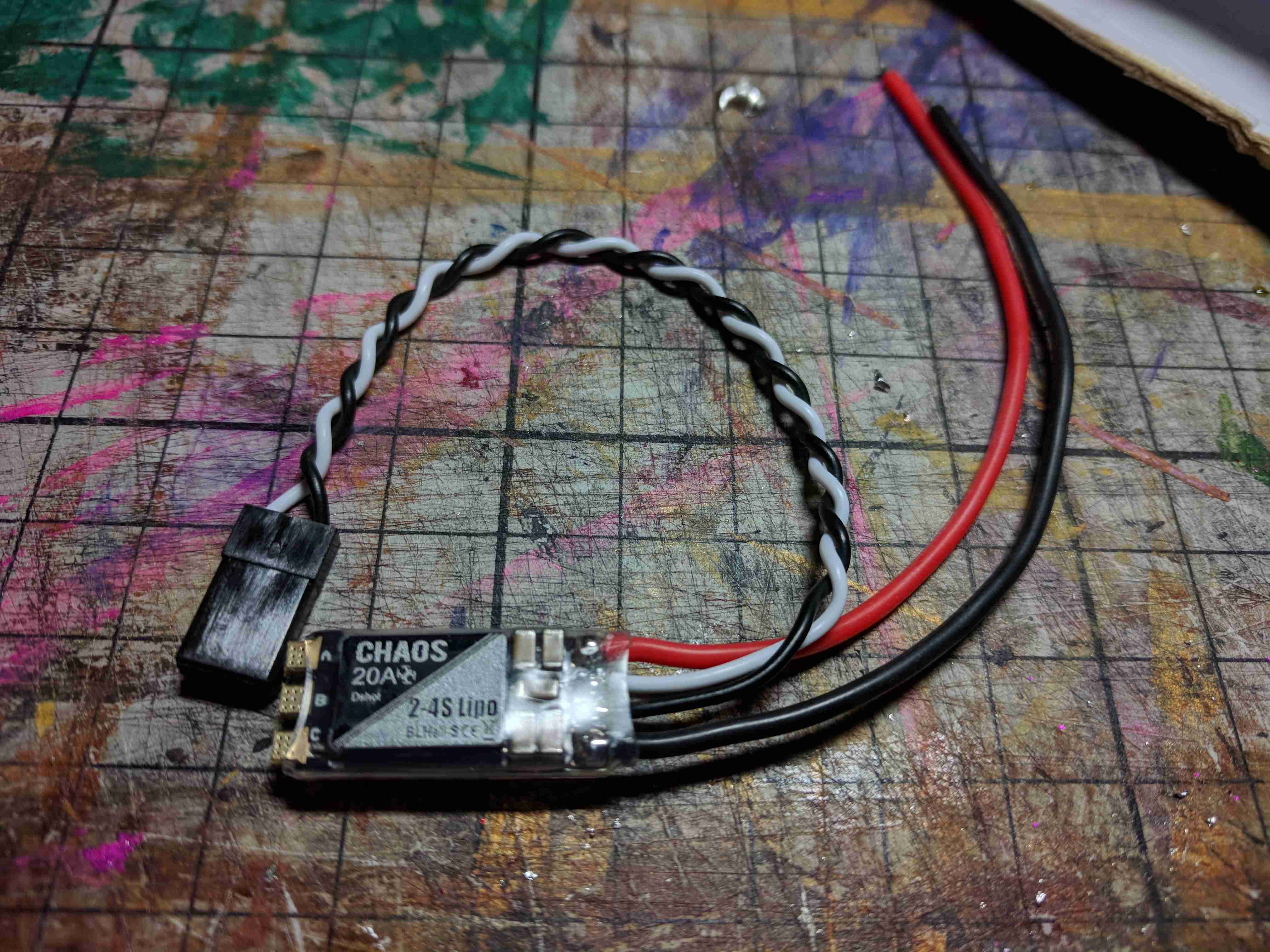
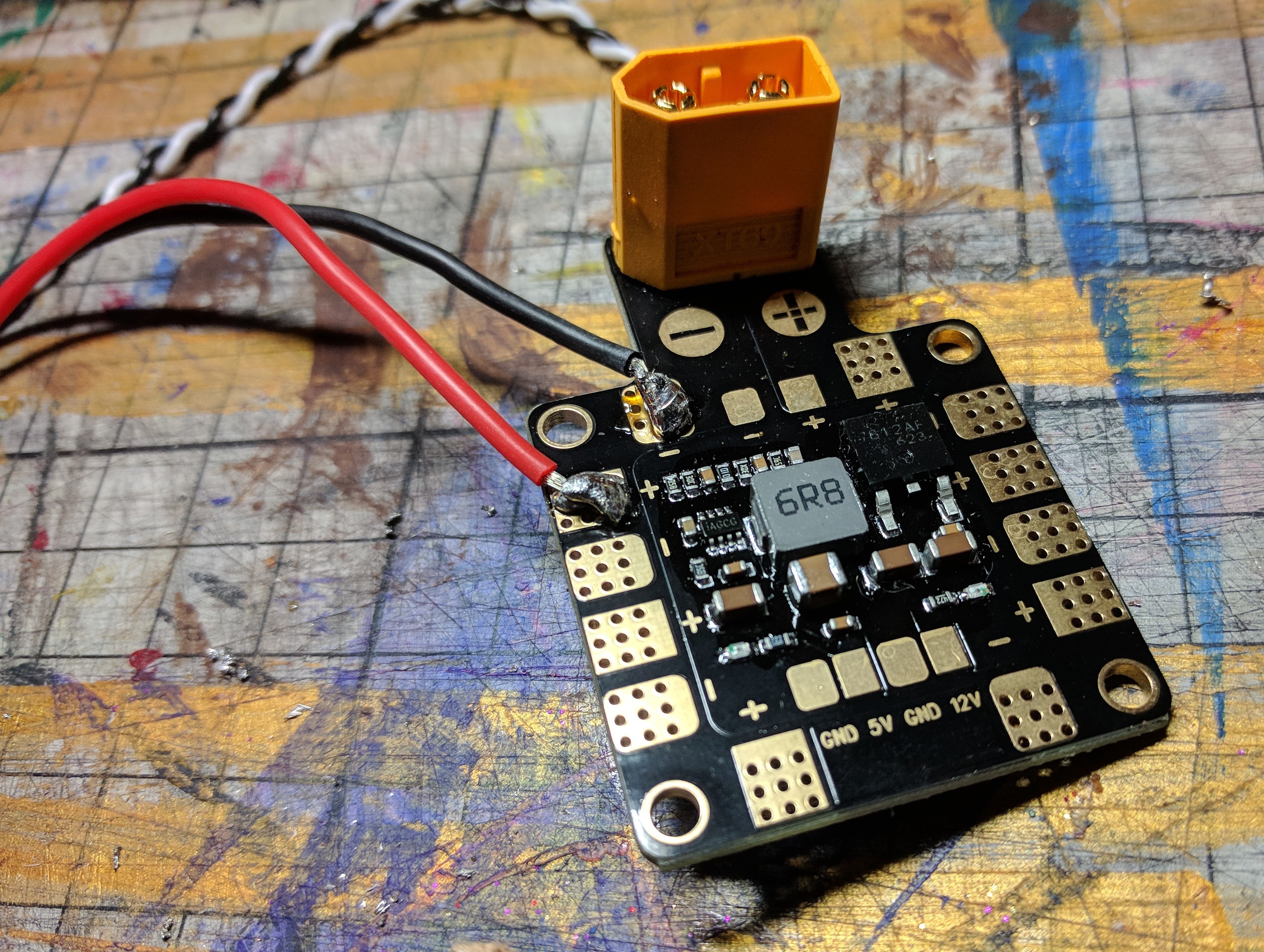
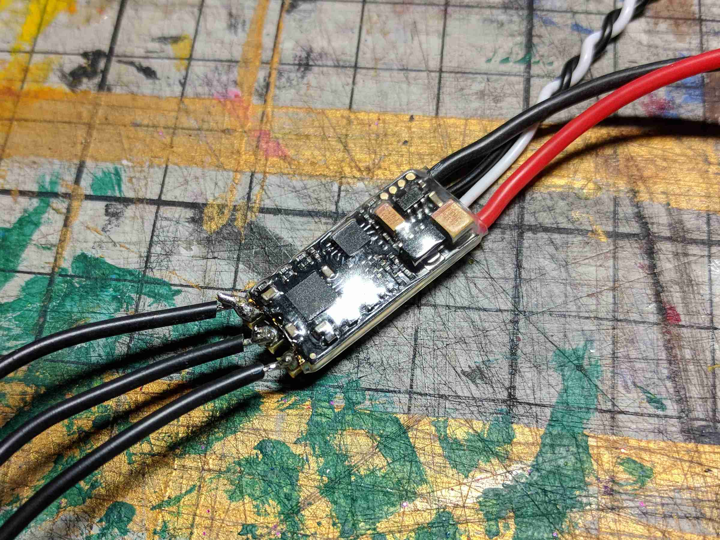
After soldering the connector to the PDB (slightly awkward given that there were just two big holes to cover with solder) I then soldered the red and black wires coming from one of the ESCs to positive and negative pads on the PDB and the three wires coming from one of the motors to the three pads on the ESC. The order of the motors wires shouldn’t matter, but it might turn out that the motor spins the wrong way. If this is the case I will have to un-solder two wires and swap them around.

Plugging the battery in again produced some very exciting beeps. I’ve since learned that the ESCs produce this noise by making the motors vibrate, which seems quite clever.

In theory I now have enough to try making the motor spin.

Motoring On

As soon as the frame was built, I wanted to attach the motors to see how it looked and check that the propellers I’d ordered would fit without hitting the frame. When I first opened one of the motor boxes I thought that the manufacturers had been exceptionally generous by providing twice as many screws as necessary. I then noticed that some are shorter than others.

I used the shorter screws to attach the motors to the frame because they seemed sufficient and the longer ones looked like they’d go further into the bottom of the motors that I was comfortable with.

There are two types of motor, or so I thought. When buying them you can usually choose either Clockwise (CW) or Anti/Counter-Clockwise (CCW), as for a quadcopter you want two propellers spinning CW and two CCW (though it might be fun to experiment with what happens if you don’t – I suspect the quadcopter will spin). I didn’t think too much about this and assumed that there was some sort of optimisation inside the motors for turning in a certain direction. Apparently the only difference is the threading on the spindle and nut such that when spinning in a certain direction, the nut will self-tighten, as opposed to undoing itself.

The motors I bought are 2300kV, which I believe means they will turn at 2300rpm per voltage of input. I have glanced over some discussions of what this means and what I took away was that a lower number will provide more power at a slower speed, and vice-versa. I’m hoping that these motors will be just about powerful enough to turn 6″ propellers fast enough to lift my quadcopter, though I haven’t done any calculations. There is a table on this page which seems to suggest that for my frame size I want to use 2000kV-2300kV motors with 6″ propellers. Ideally I would have got 2000kV motors, but the website I was ordering from had a convenient and well priced combo pack which seemed like the easiest way to get started.

Building the frame

Building the frame seemed like the logical thing to do first. It will provide a base to attach the motors to, which will allow for testing. I have read that you shouldn’t run the motors without any load attached, and I don’t have anything else to hold the motors to with propellers attached.

The instructions that came with the kit are just about sufficient to understand what to do. There are lots of parts and I was initially a bit unsure of how to proceed, however, I started at the bottom and built up. It was quite straightforward in the end and required only a small Allen key. There is a sort of canopy that goes on the top which I decided not to put on just yet as it would make it harder to access the internals and it would also add unnecessary weight.

There were a number of factors that went into choosing this frame, and I’m still a little unsure about it. From looking around, the 250mm size (measured approximately from the centre of diagonally opposite motors) is fairly popular with racing drones, so I assume that it is some sort of size category. The frame I got is 270mm which I hope will allow me to build something slightly more powerful (e.g. with larger motors and propellers) to account for the extra weight of a Raspberry Pi and Sense HAT over a standard flight controller.

Charging the battery

The first thing I could do to play with the new bits I had bought was to charge the battery.

Battery and charger

I had read a little bit about batteries before making my order. There are a number of specifications to look out for. Firstly there is the number of Ss. My understanding is that LiPo batteries are sold with different numbers of cells, with each cell producing 3.7V. Thus a 4S battery like the one I have bought produces (4*3.7) or 14.8V. According to this, the S stands for Series and it sounds like you can also get batteries with more cells wired in parallel at the same time (which would increase current at the same voltage). Motors and ESCs seem to be able to handle a range of voltages, and the higher the voltage the more power and thus thrust you can get from a particular motor/propeller combination. When looking around, it seemed like people used either 3S or 4S batteries with the size of quadcopter I was planning on building (~250mm, though I’ve bought a 270mm frame), so given that one of the comments I’ve received is “Isn’t a Raspberry Pi a bit heavy for that?”, I thought I’d go for the more powerful option.

There are other numbers that are relevant after choosing a voltage: capacity (measured in milliampere hours (mAh)) and C rating (coulombs, presumably), which refers to how fast the battery can discharge its energy. The higher the capacity, the longer the battery will last when using the quadcopter, but the battery is also likely to be bigger and heavier so it’s a trade-off. Unmanned Tech Shop suggested on one of their product pages that a 1300mAh – 1550mAh battery was suitable for a frame about the size I was looking, though I can no longer find that page (they all seem to suggest 1300mAh now), so we’ll see what happens. As for the C rating, I’m unsure of how to calculate what’s reasonable for a particular quadcopter. The one I got is 75C (which I suppose means it can deliver 75A/s, so at 14.8V that’s 1110W.. really?) but I don’t yet know if it was necessary to get that over the more common 45C batteries. The one I got seemed to be a good compromise between the different specifications and price.

The chargers require to charge LiPo batteries are known as “balance chargers”. As well as having a power output to charge the battery, they also have input sockets which you plug the battery into so that the charger can tell how charged the individual cells of the battery are. I assume that this is important because lithium batteries can sometimes catch fire and so even charging is good for safety. Some chargers also have an input for a temperature sensor to make sure that batteries do not overhead, although mine does not, so I’ll only be charging it while I’m in the room. The charger I bought can also charge at 1A, 2A or 3A. The higher the current, the faster that battery will charge, but it depends on a battery’s charging C rating (different from the discharging C rating above) as to what it can safely handle. I wasn’t aware of this when I ordered mine, and the documentation is a bit confusing (the leaflet with the battery says 1C but the battery itself says 5C) so for safety I charged at 1A. From what I’ve read, you can work out the maximum charging current by multiplying the charging C rating by the battery’s capacity, so if it’s a 1000mAh battery with a 1C charging rating, you can charge it at 1A. If it had a 5C charging rating, you could charge it at 5A.

I didn’t time how long it took to charge that battery (and I’m unsure whether it came partially charged or not), but the charger seemed to do somethings, flashed some lights (to show it was discharging individual cells) and eventually showed a green light to show that the battery was ready.

It’s arrived!

A cardboard box

It arrived! After more than a year of claiming I was going to build a quadcopter/drone, I finally ordered the parts to do so. The plan is to build a quadcopter using off-the-shelf parts, but instead of buying a flight controller I will use a Raspberry Pi 3B and attempt to write my own flight control software. This is likely to take a long time and I plan to document my progress here. My only experience with quadcopters is having a go with a small one (a Syma X11C) and I’ve never studied aviation.

It feels like it should be straightforward to write the software to make a quadcopter hover: given input from some sensors (accelerometer, gyroscope), output signals to motors to try to maintain the current position and angle, i.e.run all the motors at some speed and if the sensors suggest that one side is dropping down, increase the speed of the motor(s) on that side. I am certain that it will be more complex than that but half the enjoyment of this project will come from finding out how and why.

I’m pretty excited to get started. The first stage of the project will be putting all the components together which is like getting a new Lego kit. The next will be soldering the electronic components together and exercising my electronics interest. The last will be trying to write some code to make the thing fly, which is something I’m looking forward to a lot.

A while ago I ordered a Sense HAT for my Raspberry Pi because it contains an accelerometer, a gyroscope, a magnetometer (compass), a barometer (for altitude) as well as a hydrometer and a thermometer. It also has a super cool LED display. This seemed like a very convenient way of getting the sensor inputs I thought I needed, though it remains to be seen whether it will be sufficient. My main concerns are the speed and accuracy of the sensor data.

I had considered buying just some of the parts initially just to see whether I could get a motor to run. However, when I started adding up all the bits I would need just to do that, it seemed to make sense to just order everything at once. The motors generally used for drones of the size I was thinking seem to be 3-pole brushless motors. Due to the power requirements of these motors, it’s not possible to run them directly from the Raspberry Pi outputs. For this reason, and the need to generate accurate sequences of pulses to the three poles to make the motors turn, Electronic Speed Controllers (ESCs) are used. These devices take a higher voltage power input (generally from a Lithim-Polymer (LiPo) battery) and a signal input (e.g. from a flight controller) and generate the three signals required to drive a motor at a particular speed. Along with a motor therefore, I would also need to buy a speed controller, a battery (or a good bench power supply, ESCs can draw 30A or more) and a battery charger, just to make a motor turn. This drove my decision to buy the four motors I’d need, four ESCs, a battery, a charger, a Power Distribution Board (PDB) with a Battery Elimination Circuit (BEC), propellors and a frame to hold it all together.

I ordered from Unmanned Tech Shop as they had everything I thought I needed and for a reasonable price.

An opened cardboard box

Inside the box were the following bits:

  • 1 × SkyRC e430 LiPo/LiFe (2-4S) Balance Charger
  • 1 × RoboCat 270 Mini FPV Quadcopter Frame (White)
  • 1 × 6×30 ABS Plastic Propeller Pack (4 x CCW, 4 x CW) (Black, but one set arrived in orange, which is fine)
  • 1 × Streak Mini PDB with BEC (120A)
  • 1 × TATTU 1550mAh 14.8V 75C 4S1P Lipo Battery Pack
  • 4 × Chaos BLHeli_S Dshot ESC (20A)
  • 1 × ChaosFPV CF2205 PRO Motor Pack (2 x CW, 2 x CCW) (2300kV)

I will go into more detail about the components in later posts as I come to use them, but for now I think I might just about have everything I need to make something that can fly!