I was excited to start attempting to make the motor turn. It has proved to be more tricky than expected, however.
Everything I’d skim-read up until now had suggested that ESCs used Pulse Wave Modulation (PWM) for their input signals. This generally means creating an on-off signal at some frequency and varying the duty cycle (the amount of time an on-off signal is in the ‘on’ state) to communicate what percentage of power should be sent to the motor. I now understand that this was the case until fairly recently, but the ESCs I have bought use a digital protocol called DSHOT instead (it’s in the product name, but I had no idea what it meant at the time). As far as I can tell this protocol was conceived by some engineers/enthusiasts on a forum (the original thread, I think) and has become a somewhat popular standard for controlling ESCs for quadcopters/multicopters.
Through reading through a number of articles about the protocol (e..g here and here) I think I have a basic understanding of it. The code that runs on the ESCs is available here and the code that runs on popular flight controllers is here, so in theory it’s possible to figure out exactly what’s going on, but the ESC code is written in assembly for an architecture I’ve never studied and the flight controller software is in C which runs on an embedded system I’m also not familiar with.
Using the articles and a bit of the flight controller code I think I’ve pretty much figured out what’s expected which I’ll explain shortly. The only problem is that it’s made me realise a bit of an issue with my original plan – the protocol requires the input signal to be toggled with sub-microsecond accuracy. Given that Linux is a multi-tasking operating system, you cannot rely on your code being run uninterrupted and I’m worried that a context switch at the wrong time might lead to a physical crash.
The DSHOT protocol consists of transmitting 16-bit packets to the ESCs: an 11-bit throttle value; one bit to request telemetry (or to indicate you want to change a setting) and a 4-bit checksum. Originally, at least, there were three defined speeds for the protocol, DSHOT 150, DSHOT 300 and DSHOT 600. The numbers refer to the theoretical maximum speeds of data transfer in kilobits. Given the timing concerns above I am going to focus on the slowest version, DSHOT 150.
Each bit of a DSHOT packet is transmitted by setting the signal voltage high and then low. To communicate a ‘1’ the high portion of the wave must be longer than the low portion, and vice-versa to communicate a ‘0’. There are oscilloscope images at some of the above links which illustrate this a bit better. The eleven throttle bits are send first, starting with the most significant bit, then the telemetry bit and finally the four checksum bits. The code to calculate the checksum can be found in the cleanflight flight control software.
I haven’t found any articles listing the expected timings for DSHOT 150, but this article lists them for DSHOT 600. I them multiplied by four to get the DSHOT 150 timings, but I think they are calculated as follows:
- 150000 bits ber second = 1/150000 = ~6.67 microseconds (μs) per bit
- This matches the timings from the above article multiplied by four, so approximate timings for the waveforms are:
- T0H (time for the high portion of a zero bit) = 2500μs
- T0L (time for the low portion of a zero bit) = 4180μs
- T1H (time for the high portion of a one bit) = 5000μs
- T1L (time for the low portion of a one bit) = 1680μs

None of the articles I’ve read have explained why the timings are this way. It seems that the zero bit just needs to have a longer low portion and vice-versa for the one bit, and I think the whole idea is that the exact timings for each is not that important. This is one of the touted advantages over PWM based protocols (of which there are a few) in that timing variations do not lead to incorrect throttle values being sent to the ESCs.
Now I’ve explained how zeroes and ones are transmitted, I’ve prepared some example frames that could be sent to an ESC:
In DSHOT, the throttle values 0-47 are reserved, so 48-2047 give 2000 steps of throttle resolution. Of the reserved values, 0 is reset or disarmed and the others are various settings or requests for information. There is a concept of bidirectional communication using some output on the ESC but I’m not sure whether my ESCs have this output (certainly not without removing the shrink-wrap plastic) and I’m not interested in it for now. When sending any values 1-47 the telemetry bit should apparently be set. In the betaflight code the only settings that seem to be implemented are the spin direction (normal or reversed) but not the save settings command, so I’m not sure what’s going on. Settings commands should apparently be sent at least 10 times, presumably for reliability. It’s difficult to gather whether the things that the flight controller software do are required for interfacing with a DSHOT ESC or if it’s just best practice.
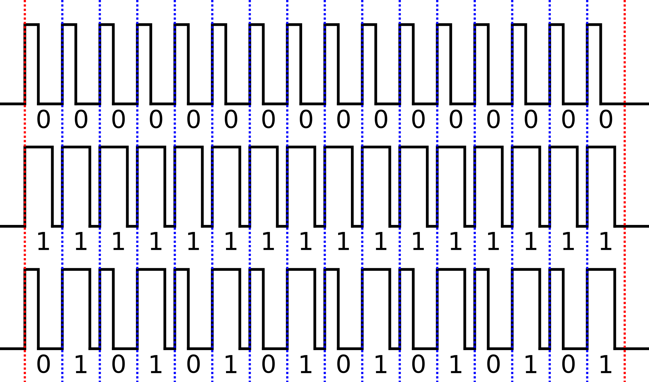
In the above image, the first frame, 0000000000000000 is the special ‘reset’ packet. I’m not sure of its precise function. The second two frames are valid throttle values, 111111111111 and 0101010101010101. These were just convenient examples and represent maximum throttle (2047) and a throttle value of 682. The second two examples include the “telemetry” bit set to one.
The last four bits are the checksum which is supposed to provide a some assurance that the bits read were the bits sent (if there were any bit misread the checksum won’t match the data). I couldn’t find the definition for this checksum anywhere other than the cleanflight/betaflight code, so here is an intuitive explanation. The related code is here:
// compute checksum
int csum = 0;
int csum_data = packet;
for (int i = 0; i < 3; i++) {
 csum ^= csum_data; // xor data by nibbles
 csum_data >>= 4;
}
csum &= 0xf;
// append checksum
packet = (packet << 4) | csum;
Taken from the cleanflight code on github.
So essentially start with 0 and XOR the 12 bits of data we want to send (11 throttle bits, 1 telemetry request bit) with that (and basically get the same thing, 0 XOR 0 = 0 and 1 XOR 0 = 1). We then right-shift the data by four bits and XOR the result with the value obtained in the previous step and repeat this again. An easier (but less generic) way of looking at it might be this:
csum = (csum_data ^ (csum_data >> 4) ^ (csum_data >> 8)) & 0xf;
The first bit of the checksum is therefore made up of the first bit of the data XORed with the 5th and the 9th, the second bit is made up of the second bit of the data XORed with the sixth and the tenth etc. In theory if any one of those bits gets read as the opposite value, the the checksum will be incorrect.
As described above, each bit takes 6680ns to transmit. This means a frame takes 16*6680=106880ns to transmit. This means that the maximum rate that we can update the ESC’s speed is 1/0.000106880=~9356Hz, however that would be with no gaps in between frames. Various articles state that the theoretical maximum update rate for DSHOT 150 is 8kHz, which would mean a (1/8000)-0.000106880=0.00001812s gap between frames (just under 2 microseconds), however the betaflight wiki page for DSHOT states that the maximum rate used for DSHOT 150 in betaflight is 4kHz. This means a (1/4000)-0.000106880=0.00014312s gap (~14 microseconds) in between frames. It sounds like the exact spacing isn’t too important and for my experimentation a lower value would be useful (to allow some time to do some other computations), so we’ll see what happens.
From the product name of the ESCs I bought (listed in the first post) you can that part of it is “BLHeli_S”. This is the firmware installed on the ESCs, and the code (in assembly) can be found here. Inside the “BLHeli_S SiLabs” directory there is a PDF manual which describes some things about the firmware, though it does not seem as if it was written to help people interface with it.
With that all out of the way, the next post will go into some experiments I’ve been trying in an attempt to control an ESC with my Raspberry Pi.
Update 2017-12-04: added a bit about update rates.
Leave a Reply